
Garage Heater Wiring Plan
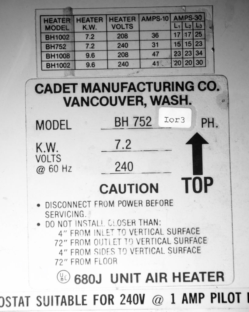
My new-to-me Cadet #BH752 electric garage heater needs a new wall thermostat and 220v connection. The unit is 17-1/2" high x 16-1/2" wide x 12" deep and has a heavy gauge steel swivel/tilt mounting bracket. It will hang from the ceiling in one corner of the new shop. The unit draws 240v and 31 amps for 7.5 KW. The fan motor is a Dayton 1/50 hp. I bought it off Craigslist for $75 from a guy in Wasilla. Manufactured in 1983, it looks pretty much unused since 1985, the year it was disconnected. When I opened it up, I was struck by how much wiring it had. It took awhile, but I was able to figure out how best to wire it in.
Parts Used
- Double-pole, 220v, 4-wire, non-programmable thermostat w/ OFF setting (Honeywell Home CT410B, $18)
- #6 aluminum (SE wire), I'll only use 3 of the 4 wires; 35' feet needed ($25)
- 40A breaker
- Knock out connectors
- J-box w/ cover
- Single gang box for thermostat
- Flex conduit w/ connectors (~4 feet) w/ connectors
- Wire nuts
- Ground screw (?)
- Electrical tape
- Long wire staples
-NoAlOx shmoo

I think this is how it should go, but change the wire gauge to #6 and breaker size to 40A based on the answers to these two questions...

Question #1: Line power comes in at left into terminals 1 and 5. But I have two dangling wires (for a single pole thermostat that has been removed) which I don't know what to do with. In my plan, I'm bringing power from the panel through the thermostat (line voltage) to the heater. How to deal with these "extra" lines?
Answer: Connect the two wires for "Single Pole Thermostat" together w/ a wire nut.
Question #2: The heater draws 31 amps. Will a 30A breaker work or do I need a 50A breaker?
Answer: #10 gauge wire handles 30 amps, while #8 wire handles 40 amps. This unit pulls 31 amps, so I'll go with a 40A breaker and slightly oversized wire - #6 aluminum SE 4-strand cable in gray jacket. The take home lesson for me is that #8 gauge wire is kind of no man's land. #10 and #6 wire are very common and widely available, but #8 doesn't come in Romex (at least it doesn't near me) and is pretty much irrelevant. And while I can probably run separate #8 THHN stranded copper wire inside EMT conduit, that's a pain and a clunky solution. The #6 SE cable behaves like Romex (several wires in one jacket), is cheap, and is available everywhere.

I used --> "4 CDR AWG 6 COMPACT AL. - AlumaFlex AA8176 Type SE Cable Style SER Type THHN 600V"

Here's those two loose wires that I will wire nut together.

Here's what the wiring actually looks like inside the heater with the cover off.

Original wiring diagram from 1983. This sheet was inside the heater housing when I opened it up.

Here are the single-phase (black text) and 3-phase (red text) options. I'm following the single phase plan. Line numbers correspond to the terminals.

Perspective sketch from the back of heater.


